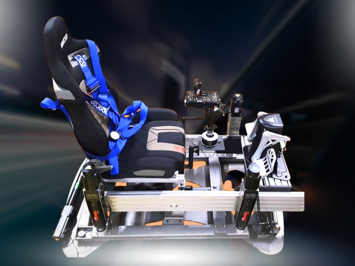

What if the movement or vibration you feel isn’t coming from the motion system at all? Flex in a simulator frame can affect how wheel forces and motion cues reach you, making it harder to tell whether your setup is performing as intended. Assessing motion simulator chassis stiffness means looking beyond the frame alone: the cockpit, wheelbase, pedals, seat and motion platform all work together under load.
A frame that feels solid when stationary may behave differently under braking, force feedback or repeated motion. The right level of stiffness depends on your equipment and how it’s mounted, not simply on the material or a “zero flex” claim. Start by identifying what moves, where it moves and what you were doing when it happened.
This guide explains how chassis flex can influence feedback, compares common tubular steel and aluminium profile designs, and gives you a practical way to assess a rig you own or are considering. You’ll also learn how to distinguish possible frame movement from motion system behaviour, so you can make a more informed decision about what your simulator setup needs.
Key Takeaways
- Learn to distinguish elastic frame flex from loose connections, vibration and the intended movement of a motion platform.
- Trace how force travels through your wheelbase, pedal mounts, frame, seat and motion platform to help pinpoint unwanted movement.
- Compare profile, tubular and steel frame designs by looking at geometry, bracing, joints and mounting points, not material alone.
- Use a practical inspection sequence to check fasteners and test the wheelbase, pedals and seat separately.
- Assess motion simulator chassis stiffness as part of your complete setup, considering hardware loads, mounting geometry, motion and future adjustments.
What does motion simulator chassis stiffness actually mean?
Motion simulator chassis stiffness is the frame’s resistance to unwanted bending or twisting when forces act on it. In a rig, those forces come from your hands at the wheel, your feet on the pedals, your body in the seat and the motion system beneath the cockpit. The frame doesn’t need to be absolutely immovable. It needs to keep the controls and seat working together predictably under the loads your equipment produces.
Think of the rig as one connected load path. Force applied at the wheelbase travels through its mount and the frame. Braking force passes from the pedal plate into the structure. The seat and motion platform are part of the same assembly, so the frame’s geometry, joints and attachment points affect how loads travel between them. That whole-system view matters particularly in a motion simulator, where intended platform movement is part of the experience, not evidence of a fault.
Keep four different behaviours in mind. Elastic flex is temporary bending or twisting under load, which generally returns when the force is removed. Looseness is unwanted play at a joint or fastener. Vibration is repeated movement, which may come from motors or other equipment as well as the frame. Designed motion is movement produced by the platform to create a cue. A moving seat, then, doesn’t automatically mean the chassis is flexing.
How is chassis stiffness different from strength and weight?
These terms describe different things. Stiffness is how much a component deflects under a given load; strength is how much load it can withstand before permanent damage or failure; mass is how much it weighs. A pedal plate might withstand hard braking yet still flex enough to feel less stable. Likewise, a heavy frame isn’t necessarily stiff: its shape, unsupported spans, bracing and connections all influence how it behaves. Adding material or weight alone doesn’t guarantee a more rigid cockpit.
Why does stiffness matter in a motion simulator?
Consistency is the goal. If the wheelbase mount bends noticeably relative to the seat, some movement from your hands may be absorbed by the structure instead of feeling like a direct response from the wheel. If the pedal assembly shifts under braking, your feet can move relative to the seat. Frame movement can also complicate motion cues if the seat and controls don’t maintain their intended relationship. This doesn’t mean every movement is harmful: the platform is meant to move, and minor vibration can have other causes. Assess the whole setup, including its hardware, geometry, joints and use, rather than judging stiffness by material alone.
How chassis flex changes motion and force-feedback signals
Forces travel through the whole rig, not just the component where they begin. Wheel torque passes from the wheelbase into its mounting plate, then through the frame and supports. Braking force travels from the pedals through the pedal plate and chassis. The seat, frame and motion platform complete the assembly, so movement at one connection can affect how the controls and seat relate to each other.
If a mount or frame section bends under load, some movement occurs within the structure rather than solely where you expect it. That can make steering or braking feel less consistent, because the wheelbase, pedals and seat may shift slightly in relation to one another. Unwanted chassis flex can make control feedback less consistent by allowing the frame to move between the force-generating hardware and the driver. This is a possible effect, not a guarantee that every flexing component will noticeably alter your experience.
Where do unwanted movement and flex usually appear?
Pay particular attention to wheelbase mounts, pedal plates, seat supports and bolted connections between frame sections. A long unsupported span can deflect more readily than a shorter, well-supported one, while a corner with limited bracing may move or twist under force. Look for movement that repeats when steering or braking, visible gaps or shifting joints, and changes in how the seat lines up with the controls. These are clues, not a diagnosis: fasteners, vibration or another component may be responsible.
To narrow down the source, observe each area separately under a controlled, modest load. If the wheelbase mount moves while the rest of the frame appears still, investigate that connection first. If a seat support shifts relative to the pedal assembly, look elsewhere in the load path. Avoid assuming that actuator travel or a vibrating motor is frame flex. Note where movement occurs and what triggers it.
How do motion systems change chassis demands?
A fixed rig mainly responds to forces applied through its controls and the driver. A moving system adds changing loads as the platform accelerates, tilts or changes direction, so compatibility between platform, frame, mounts and seat matters. Platform movement is intended; bending or looseness within the cockpit is a separate behaviour. The demands depend on the specific hardware and how the assembly is supported, so motion alone doesn’t establish whether a frame is sufficiently stiff.
For context on how platform movement is designed, Race@Home’s 6 DOF motion simulator guide explains the broader motion system concept. The same whole-assembly thinking applies when considering Race@Home motion platforms: assess how the cockpit, mounting points and platform work together rather than treating motion simulator chassis stiffness as a standalone material choice. For wider engineering context, the IEEE Transactions on Robotics covers research in robotics and control, fields relevant to understanding how moving systems are designed and controlled.
Comparing motion simulator chassis designs without chasing “zero flex”
A frame’s material is only one part of its behaviour. To compare designs, look at how the structure carries loads from the wheelbase, pedals, seat and motion mounts. Section size, unsupported lengths, bracing, joint design and the position of mounting points all affect how the complete rig responds. A “zero flex” claim is meaningful only when you know what was tested, where force was applied and how movement was measured.
| Design approach | Practical considerations |
|---|---|
| Aluminium profile | Modular sections and slot-based connections can make component positions easier to adjust. Rigidity depends on profile dimensions, spans, bracing and how joints and mounts are assembled. |
| Tubular frame | Joined tubes can create a compact, shaped layout, but mounting options depend on the frame’s design. Consider how wheelbase, pedal and seat supports attach, and whether their positions can be changed easily. |
| Fabricated steel frame | Welded or bolted steel sections can be arranged around specific mounting points. Check the section sizes, bracing and connection details; the material label alone doesn’t show how the finished frame responds to load. |
What should you compare between profile, tubular, and steel frames?
Start with the layout. Look for long spans without support, corners that rely on a single connection, and mounts that place force far from the main frame rails. Then consider how each design joins its parts: adjustable connections offer flexibility, while fixed joints may limit repositioning. Neither approach guarantees a particular result. The OptimumG technical papers on chassis stiffness offer broader engineering context for thinking about chassis behaviour and torsional stiffness.
Next, check how the frame accommodates each component. Can the wheelbase mount sit securely where you need it? Can the pedal plate and seat supports be positioned without creating long unsupported sections? If a motion platform is part of the setup, its mounts must also suit the frame layout. These details can matter more than whether the chassis is described simply as aluminium, tubular or steel.
When is a more rigid or adjustable frame the better fit?
Your installed hardware and intended use should guide the choice. A setup with forceful braking, strong wheel feedback or a motion platform places different demands on its mounts and structure than a lighter fixed cockpit. Adjustability is useful if you expect to change your seating position or components; after each adjustment, the connections still need to be secure and well supported.
Compare the full assembly, including the room available for the rig and access to fasteners or mounting slots. A compact layout may suit a restricted space, while a modular design may offer more scope to reposition components. There’s no universal winner: motion simulator chassis stiffness depends on how frame geometry and connections work with your hardware. Race@Home’s sim racing setup guide explores broader compatibility considerations for building a motion rig.
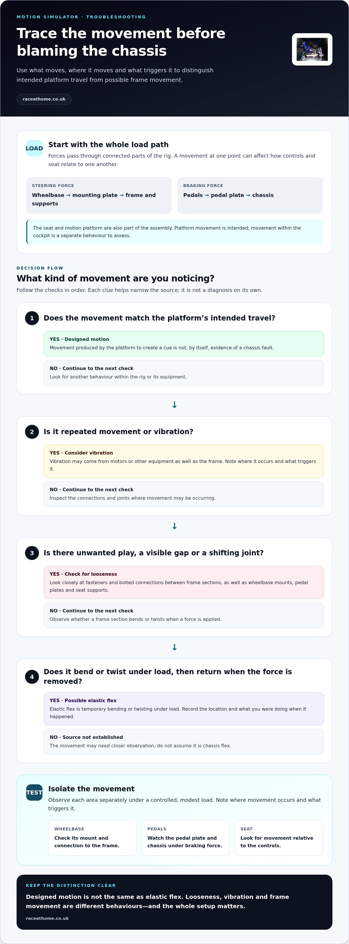
How to inspect and assess motion simulator chassis stiffness
A useful assessment doesn’t need a force gauge or a risky stress test. Start with the rig switched off and stationary, then observe it during normal use. The aim is to locate where movement appears and whether it repeats, not to push the frame beyond its intended loads. If a motion system is active, keep clear of moving parts and follow its operating guidance.
Which checks help identify flex in an existing rig?
Work through the assembly in order. Look for visible gaps, loose fasteners, cracked or shifting brackets, and connections that may have settled. Don’t tighten components blindly; follow the relevant assembly instructions, since fastener requirements can vary.
- Inspect the connections. Check bolted frame joints, brackets and supports for looseness or visible movement.
- Observe the wheelbase mount. During ordinary steering, look for movement of the mount relative to the frame.
- Check the pedal assembly. Under normal braking, watch whether the plate or its supports shift.
- Observe the seat supports. Notice whether the seat moves relative to the frame or control positions.
- Record what you see. Note the location, direction and circumstances of movement before adjusting anything.
Check one area at a time. A wheelbase plate that moves while the surrounding frame remains still points to a different place to investigate than a seat support that shifts with the pedal assembly. These observations help narrow down the possibilities, but they don’t prove the source on their own.
How can you separate chassis flex from other causes?
Movement can come from a loose fitting, an interface between components, vibration from equipment or intended actuator travel. Compare what moves with what should move: platform travel is part of a motion system’s operation, while a shifting joint or mount may need closer inspection. Avoid diagnosing the entire chassis from a single sound or sensation.
Change one variable at a time. For example, note the behaviour before and after checking a connection, rather than changing seat position, pedal position and wheelbase settings together. This makes it easier to see whether the symptom changes with a particular adjustment. If movement is sudden, unusual or accompanied by a damaged part, stop using the affected equipment and follow its manufacturer’s guidance.
Quick checklist: inspect connections first; observe the wheelbase, pedals and seat separately; use normal operating loads; distinguish platform travel and vibration from frame movement; record repeatable symptoms; alter one variable at a time. This gives you a practical basis for judging motion simulator chassis stiffness before comparing replacement options. For purchase-stage context, Race@Home’s motion rig value guide can help you weigh a motion setup against your wider simulator plans.
If you’re exploring motion hardware alongside your chassis assessment, explore Race@Home motion platforms as part of your complete rig planning.
Choosing a motion simulator chassis that suits your complete setup
Choose a chassis by working out how the whole simulator will fit and function, not by chasing a material label or an unqualified “zero flex” claim. The right decision depends on the loads from your controls, where components mount, how the motion system connects, the space available and whether you plan to adjust or upgrade the rig. A frame is one part of a connected system.
- Start with your hardware. Consider the wheelbase and pedals you use, how forcefully you brake, and the seat and control positions you need. Those details help identify which mounting areas need particular attention.
- Map the mounting geometry. Check how the wheelbase, pedal plate and seat attach to the chassis. Consider whether supports sit close to the main frame structure or rely on long spans, and whether adjustments can be secured in the position you want.
- Plan for the motion system. Look at how the platform and chassis are intended to connect, and how the complete assembly will move. Don’t assume that a frame’s material or advertised rigidity alone establishes compatibility.
- Measure the room and consider future changes. Allow for the rig’s footprint and movement, as well as access to components. Think about whether you may reposition controls or change hardware later.
What should you match before selecting a motion platform?
Compare the chassis mounting points with your intended wheelbase, pedal and seat layout, then consider how the motion platform fits beneath or around that structure. The footprint matters too: a setup that suits the room while stationary must still have appropriate space for its intended movement. Treat compatibility as a question about the assembled rig, not a single dimension or frame material. If one connection or support is overlooked, you may need to revisit the rest of the plan.
How does a hand-built motion platform fit the decision?
Race@Home hand-builds LowSlider 6 DOF and 3DoF motion platforms to order. The LowSlider design has an ultra-low profile and compact footprint, details that can inform how you plan the rig’s overall height and available space. They don’t, by themselves, establish how a particular chassis will mount or perform with a given setup. Consider your frame, component positions and intended motion together, and use the motion simulator buying guide for broader purchase considerations.
That system-first approach keeps motion simulator chassis stiffness in perspective: assess the structure in relation to your hardware and intended use, rather than relying on “zero flex” language without test conditions. Once you’ve mapped your requirements, explore Race@Home motion platform options as a next step in planning a motion setup.
Plan your next step around the whole rig
Before changing your setup, decide what you want the simulator to do next. You might be refining control feel, adding motion or planning for different hardware. Use that goal to guide your priorities, then consider how every component will fit and work together. That’s a more useful starting point than chasing a material label or an unqualified rigidity claim.
Keep motion simulator chassis stiffness in view as you compare platforms, mounts and available space. Race@Home hand-builds LowSlider motion platforms to order, with 6 DOF and 3DoF configurations. The LowSlider design has an ultra-low profile and compact footprint, details to factor into your overall rig plan.
Ready to explore what could suit your simulator? Explore Race@Home motion simulator platforms and take the next step towards a setup shaped around your hardware and the experience you want.
Frequently Asked Questions
Is a stiffer chassis always better for a motion simulator?
No. More stiffness can help limit unwanted movement, but it isn’t a complete measure of simulator quality. Judge motion simulator chassis stiffness in context: how forces travel through your assembled rig, where the wheelbase and pedals attach, how the motion system moves, and what you want from the setup. A frame suited to one combination of controls and platform may not suit another. Focus on a stable, compatible system, not an abstract maximum.
Can chassis flex affect direct-drive force feedback?
It can, depending on where and how much movement occurs. If a wheelbase mount shifts relative to the frame, your steering input may move the mount as well as transmit force through the cockpit. That’s different from the wheelbase’s normal feedback or vibration from motors and other components. Inspect the mount alongside its joints and nearby supports; movement at one point doesn’t establish how the whole rig will feel on track.
Does a heavier motion simulator chassis have to be stiffer?
No. Weight describes mass, not how much a frame bends under load. A heavier chassis may still have a long unsupported section or a flexible mounting plate, while a lighter layout may use geometry and bracing effectively. Compare the material sections, joints and load paths instead of treating weight as a shortcut. Also consider how the frame’s mass and footprint suit the intended motion platform and the space available for your rig.
Can I fix a flexing sim racing chassis by tightening its bolts?
Sometimes, if the movement comes from a loose connection. Check joints and fasteners for visible movement, then follow the assembly maker’s guidance for any adjustment. Don’t overtighten: excessive force can damage threads or components. If the bolts are secure but a pedal plate or long frame section still moves under ordinary use, tightening may not address the cause. Make one change at a time and observe whether the same movement changes.
Are aluminium profile chassis rigid enough for motion simulators?
They can be suitable, but the material name alone can’t answer that. Consider the profile dimensions, frame layout, bracing, connectors and the location of wheelbase, pedal, seat and platform mounts. For example, a profile rig may offer useful adjustment, but its behaviour still depends on how the sections are joined and supported. Assess the complete assembly against your hardware and intended motion rather than assuming every aluminium frame performs alike.
How can I tell whether movement comes from the chassis or motion actuators?
Observe the rig during normal operation and note which parts move in relation to one another. Actuator travel should correspond with platform movement; shifting at a wheelbase mount, pedal plate, seat support or frame joint may point elsewhere. Record when the movement happens and whether it repeats, then change one setup variable at a time. A single observation can narrow down where to investigate, but it may not identify the cause conclusively.


