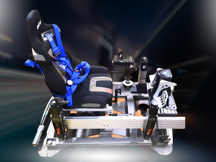

The actuator isn’t the first thing to assess when planning an aluminium profile rig motion upgrade. Start with the connection between your cockpit and the motion platform. If the frame, mounting points and available space don’t suit the arrangement, impressive hardware won’t make a coherent setup.
Adding physical feedback doesn’t have to mean replacing a cockpit that already works for you. First establish whether the frame and its layout can accommodate movement, what may need to change, and whether those changes solve a real problem.
This guide takes you through the practical checks: frame layout, mounting, clearances, cable routes and the equipment you want to keep. You’ll also compare static, adapted and purpose-built options, including Race@Home’s LowSlider platforms. The aim is to plan an upgrade that preserves the strengths of your current cockpit while bringing simulation forces into sharper physical focus.
Key Takeaways
- Understand how a motion platform changes a static aluminium cockpit and what that means for your setup.
- Record your rig’s footprint, profile layout, seat position and planned platform location before comparing options.
- Compare keeping your cockpit static, adapting its mounting arrangement or considering a purpose-built platform.
- Document component positions, cable routes and access needs before making changes.
- Explore Race@Home LowSlider 3DoF and 6 DOF platforms, designed with a low profile and compact footprint.
Aluminium Profile Rig Motion Upgrade: What Changes When You Add Movement?
A motion upgrade adds hardware that moves the cockpit in response to simulation inputs. Instead of staying fixed, the rig can move to provide physical cues linked to events on track. The movement depends on the platform and its configuration, so an aluminium extrusion frame alone won’t tell you what the finished setup will do.
In a static cockpit, the frame, seat, wheel and pedals stay in place while you drive. With motion hardware, the cockpit connects to a moving platform. This changes how the assembly behaves and how much room it needs. The aluminium profile is only one part of the equation: dimensions, layout and mounting interfaces all affect how the components work together.
What does a motion platform add to a profile rig?
A motion system can translate simulation events into movement you feel through the cockpit. Depending on the system and its setup, braking, cornering or changes in track surface may be represented by movement. These cues complement the steering wheel’s force feedback, which produces forces through the wheel itself. They contribute to the same driving experience, but they are different feedback channels. For a wider overview of how a motion simulator produces movement, consider the different movement axes and applications described in this reference.
The appeal is a more physical connection between what the simulation reports and what you feel. Don’t assume a particular cue will feel identical across platforms or configurations: the motion hardware, cockpit arrangement and system setup all shape the result.
Why the frame-to-platform interface matters
The mounting interface connects your cockpit structure to the motion hardware. Its fit depends on the rig’s dimensions and profile layout, as well as the platform’s intended configuration. A rigid profile frame may still need a suitable way to attach to a particular platform. The material alone doesn’t establish compatibility.
Assess a motion upgrade as a complete assembled system. Consider more than the attachment points. The moving rig must accommodate the relevant loads, and you need to account for clearance around the seat, pedals, wheel, cables and surrounding space. A component close to the floor or another part of the cockpit may need particular attention once the platform moves.
Start with the cockpit as you actually use it, including the seat and equipment in their normal positions. The frame-to-platform connection is the first design question, but it isn’t the only one. Check the proposed arrangement against the overall cockpit dimensions, access needs and available space. This helps you distinguish a workable upgrade path from one that looks compatible only when you view the bare aluminium profiles.
For broader context, moving from a static rig to motion means thinking beyond the platform itself. A well-planned aluminium profile rig motion upgrade treats the frame, mounting arrangement and surrounding equipment as one setup. Begin by measuring the assembled cockpit before deciding how to adapt it.
How to Assess an Aluminium Profile Rig Before Adding Motion
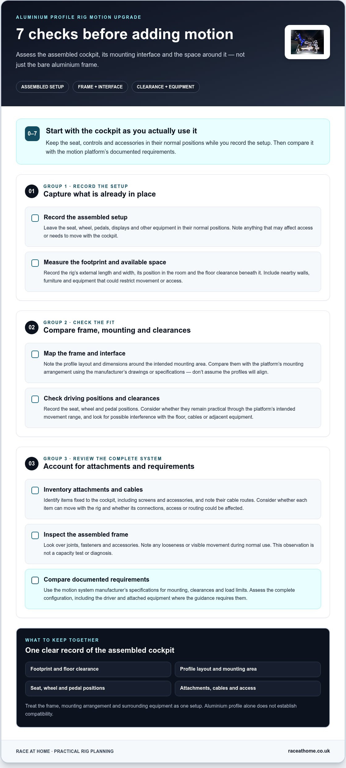
Assess the cockpit as you drive it, not as a bare frame or a layout you might adopt later. Record how the seat, controls and accessories fit together, then compare that arrangement with the motion platform’s documented requirements. Work through these checks in order and keep the measurements together.
- Record the assembled setup. Leave the seat, wheel, pedals, displays and other equipment in their normal positions. Note anything that could affect access or needs to move with the cockpit.
- Measure the footprint and available space. Record the rig’s external length and width, its position in the room and the floor clearance beneath it. Include nearby walls, furniture and equipment that could restrict movement or access.
- Map the frame and interface. Note the profile layout and dimensions around the intended mounting area. Compare this with the platform’s mounting arrangement, using the manufacturer’s drawings or specifications rather than assuming the profiles will align.
- Check driving positions and clearances. Record the seat, wheel and pedal positions. Consider whether they remain practical through the platform’s intended movement range, and look for possible interference with the floor, cables or adjacent equipment.
- Inventory attachments and cables. Identify items fixed to the cockpit, including screens and accessories, and note their cable routes. Consider whether each item can move with the rig and whether its connections, access or routing could be affected.
- Inspect the assembled frame. Look over joints, fasteners and accessories. Note any looseness or visible movement during normal use. This is an observation, not a capacity test or diagnosis.
- Compare documented requirements. Use the motion system manufacturer’s specifications for mounting, clearances and load limits. Assess the complete configuration, including the driver and attached equipment where the manufacturer’s guidance requires them.
Check geometry, mounting points and clearance
Measurements are more useful than judging compatibility by profile material or appearance. Sketch the cockpit from above and from the side, marking its outer dimensions, mounting locations and floor clearance. Compare the proposed interface with the existing profile layout. If a seat, pedal deck or wheel assembly sits near the platform’s intended movement area, record that relationship instead of assuming it will remain clear.
Review frame rigidity and the complete setup
Inspect the assembled cockpit, including its joints, fasteners and accessories. Note flex or movement you observe in ordinary use, but don’t treat that observation as proof of safe load capacity. Compatibility depends on the complete rig and interface, not profile material alone. Use the platform manufacturer’s specifications to assess capacity and mounting requirements for your configuration.
A careful record gives you a practical basis for comparing options without changing components prematurely. If a purpose-designed platform is on your shortlist, compare Race@Home LowSlider motion platforms with your measurements and interface notes.
Which Motion Upgrade Route Suits an Aluminium Profile Cockpit?
There isn’t one upgrade path for every profile cockpit. Your choice depends on which parts of the rig you want to keep, how its mounting arrangement relates to the motion hardware, and whether the complete setup suits your space and equipment. Compare the routes against your measurements. Use the manufacturer’s specifications to resolve fit and load requirements rather than relying on assumptions.
A static setup remains a valid choice if movement isn’t a priority. If it is, retaining your existing cockpit may be practical when its geometry and interface suit the intended arrangement. A purpose-built platform is another option to evaluate as part of a complete setup. The sim racing setup guide provides broader context for how cockpit components relate to one another.
| Route | Requirements | Potential advantages | Trade-offs | Information still needed |
|---|---|---|---|---|
| Keep the cockpit static | No motion-platform interface is needed. | Preserves your current arrangement and avoids changes to the cockpit. | Doesn’t add platform-driven movement. | Whether a static setup still meets your priorities. |
| Adapt the existing mounting arrangement | The rig geometry and proposed interface need to align with the chosen configuration. | May let you retain more of your existing cockpit and equipment. | Adaptation depends on the specific frame and platform. Changes may affect fit, clearance or access. | Manufacturer’s mounting drawings, documented requirements and the complete assembled configuration. |
| Evaluate a purpose-built motion platform | Assess the platform alongside the cockpit, room layout and attached equipment. | Lets you consider the motion system as part of a planned configuration. | May require a different arrangement from your current static setup. | Interface, clearances, load guidance and how the proposed arrangement accommodates your equipment. |
Adapt the existing rig or start with a motion platform?
Keeping your cockpit may suit you if its dimensions and mounting interface align with your upgrade plan. Adaptation depends on the configuration, so don’t assume that drilling, reinforcement or repositioning is necessary or suitable. Compare the existing frame with the platform’s documented interface. You can also evaluate a complete platform around the cockpit arrangement you intend to use, including its seat, controls and accessories.
Choosing between a 3DoF and 6 DOF platform
3DoF and 6 DOF describe distinct platform categories, but the label alone doesn’t establish how a particular system integrates with your rig. Focus on the platform’s specifications, mounting arrangement and requirements for your intended configuration. Race@Home offers LowSlider 3DoF and 6 DOF motion platforms. The 6 DOF motion simulator guide explores the broader platform context.
For an aluminium profile rig motion upgrade, choose an option that preserves a coherent cockpit and has a clearly understood interface. Resolve the mounting and configuration questions first, then compare the movement category with your aims.
Prepare Your Aluminium Profile Rig for a Motion Upgrade
Preparation means making the intended arrangement clear before anything moves. A measured plan helps you spot practical conflicts early, such as a cable that could pull tight or a control that may become difficult to reach. Base modifications on the verified requirements of the platform and rig, rather than generic assumptions about profile frames or mounting methods.
Plan space, cable routing and equipment access
Measure the assembled cockpit in its normal driving configuration, then use the motion platform’s guidance to account for its intended movement envelope. Consider the space around the rig as well as its footprint. Trace each cable from the device to its connection point and note where movement could cause tension, snagging or restriction. Check that controls, power connections and adjustment points will remain accessible in the planned position.
- Record the overall length and width of the assembled rig, including attached equipment.
- Note nearby walls, furniture and other obstacles that could affect movement or access.
- Map cable routes and identify connections that may need room to move with the cockpit.
- Check access to controls, power connections and adjustment points in the proposed arrangement.
- Mark the intended cockpit position on your room plan, including space needed to get in and out.
Don’t reposition components just to make a drawing look tidy. If the seat, wheel or pedals need to move, record their current positions first, then compare the revised layout with the platform’s documented requirements.
Make a clear pre-upgrade record
Before changing component positions, photograph the rig from several angles, including the mounting area, cable runs and connections. Add brief notes about dimensions and key adjustment points. A record of the starting layout makes integration decisions easier to review.
- List the installed seat, wheelbase, pedals and display or VR equipment.
- Record each component’s current position and any adjustments that suit your driving posture.
- Note accessories attached to the frame and connections that could affect movement or access.
- Keep the platform’s specifications with your measurements so you can compare its requirements with your actual setup.
This record is useful when deciding whether to retain the cockpit as it is or alter its configuration. It gives you a reference point for each proposed change and helps avoid unnecessary modifications. Base drilling, reinforcement or other structural changes on the relevant manufacturer’s instructions for the specific rig and platform, not a general rule for aluminium profiles.
Race@Home designs and hand-builds LowSlider motion platforms with a low profile and compact footprint. Consider this design as you plan your setup, and explore Race@Home LowSlider motion platforms as part of your upgrade research.
Explore Race@Home LowSlider Motion Platforms for Your Upgrade
Once you’ve assessed your cockpit and recorded its measurements, compare your intended setup with the motion platform’s documented requirements. Race@Home designs and hand-builds LowSlider motion platforms, including the LowSlider 3DoF motion platform and the LowSlider 6 DOF Twin-Traction-Loss Motion Platform. These are distinct options to consider as you plan how movement could become part of your sim racing setup.
The LowSlider design has an ultra-low profile and compact footprint. This form factor is relevant when planning space around a cockpit, but it doesn’t guarantee a fit with every aluminium profile rig. The key question is how the platform, mounting interface and fully equipped cockpit work together in your intended configuration.
How LowSlider fits into the upgrade decision
Bring your earlier checks into the platform evaluation. Compare the rig’s dimensions and profile layout with the platform’s documented requirements, then consider the seat, controls, displays, cables and available room as parts of the same arrangement. If the interface and configuration align, you’ll have a clearer basis for deciding whether to retain your cockpit or plan a different arrangement.
Don’t treat the profile material or a compact design as proof of compatibility. Fit depends on the complete cockpit setup and verified requirements, including the mounting arrangement and relevant clearances. Keep those details with your measurements so you can assess the LowSlider options against the rig you intend to use, rather than a simplified frame layout.
Race@Home platforms are hand-built to order and ship worldwide in four pieces for customer assembly. The full setup can be completed in under an hour. These details describe the assembly approach; you should still assess the interface and configuration against your cockpit.
What to explore next
Use your rig record as a comparison sheet. Set out the cockpit’s footprint and mounting layout, identify attached equipment, then compare those details with the motion platform’s published requirements. Note anything that affects the arrangement, such as available space around the rig or access to connections. This keeps the decision grounded in your intended configuration, not assumptions about what a profile cockpit can accommodate.
- Compare your measurements with the platform’s documented requirements.
- Consider how your complete cockpit arrangement relates to the mounting interface.
- Review the LowSlider 3DoF and 6 DOF options in light of your intended setup.
A considered aluminium profile rig motion upgrade begins with a clear picture of the cockpit you want to move. With your measurements and configuration in hand, compare them with the LowSlider motion platform range as you plan a more immersive setup.
Turn Your Upgrade Plan into a More Immersive Cockpit
Your next move doesn’t have to be a wholesale rebuild. Decide what matters most in the experience you want, then use that priority to guide your platform choice. A clear design brief helps separate essential changes from tempting modifications that don’t solve a specific problem.
For an aluminium profile rig motion upgrade, progress comes from turning your plan into a coherent configuration. Keep the driving position and equipment that work for you at the centre of the decision, and let verified requirements shape any changes. The goal isn’t simply to add movement. It’s to create a considered setup where physical feedback strengthens your connection to the simulation.
When you’re ready to explore a purpose-built option, compare your intended configuration with the platform information. Explore Race@Home LowSlider motion platforms and plan your next step towards a more immersive cockpit.
Frequently Asked Questions
Can I keep using my existing sim racing software after adding a motion platform?
Usually, you can keep using your existing racing software, but motion feedback also depends on a compatible route for sending simulation data to the platform. Support can vary by game, motion system and control software, so check the documentation for the exact combination you plan to use. A title may continue to run normally even if its data isn’t supported by a particular motion-control setup.
Can I use VR with a motion-upgraded aluminium profile rig?
VR can be part of a motion sim racing setup, provided the headset, motion system and relevant software work together. Don’t assume compatibility from the headset or cockpit alone; review the requirements for each component and the simulation title. If movement feels uncomfortable in VR, reduce the motion intensity or pause the session. A gradual introduction can help you judge how the combined visual and physical cues feel.
Does adding motion change how I should position my seat and pedals?
There’s no single seat or pedal position that suits every driver, but movement makes a comfortable, repeatable driving posture especially useful. Set the seat so you can reach the pedals without overextending your legs, and maintain a relaxed grip on the wheel. If you adjust either component during integration, reassess your posture in the cockpit and record the preferred settings so they’re easy to restore.
Will a motion platform make a sim racing rig noisier?
A motion platform can add mechanical sound or vibration, but the amount depends on the system, its operation and how the setup interacts with the floor and room. Sound may be more noticeable in a quiet space or if nearby objects vibrate. Consider where the rig sits and whether its movement could disturb others. Follow the platform’s instructions for placement and operation rather than adding improvised dampening.
Can I move a motion-upgraded rig after assembly?
Possibly, but don’t assume the assembled cockpit and platform should be moved as one unit. Their combined weight, shape and connections can make repositioning difficult. Before moving anything, follow the platform manufacturer’s guidance on powering down, disconnecting cables and handling the equipment. If the instructions call for partial disassembly, document connections and component positions first, then reassemble and inspect the setup as directed.
Does an aluminium profile rig need extra reinforcement for motion?
Not automatically. Whether any change is needed depends on the particular frame, platform interface and complete configuration, so generic advice to reinforce every aluminium profile rig isn’t reliable. For an aluminium profile rig motion upgrade, compare the platform’s published mounting and load requirements with the rig manufacturer’s guidance. Don’t drill, brace or alter the frame based on guesswork; follow the specifications that apply to your equipment.


